
HAZOP preparation: defining nodes and pre-filling the worksheet
A HAZOP is only as good as its preparation. Before the team sits down, someone has to split the P&IDs into nodes, write down what each part of the plant is meant to do, and gather the safeguards the drawings show. This guide covers how that is done, what can safely be prepared in advance, and what must be left to the session.
What IEC 61882 asks for
The international standard for the method is IEC 61882:2016, Hazard and operability studies (HAZOP studies) – Application guide. Its vocabulary is slightly different from everyday use, and it helps to know both:
- A part is the "section of the system which is the subject of immediate study". In process HAZOPs, the parts are usually called nodes — a line, a vessel, a pump and its piping — though "node" is not a term the standard defines.
- The design intent is the "designer's desired, or specified range of behaviour" for the part's properties: what the node is supposed to do, and within what limits.
- A guide word is a "word or phrase which expresses and defines a specific type of deviation from a property's design intent". Applied to a property (flow, pressure, temperature, level, composition), it gives a deviation to examine.
The standard gives example guide words rather than a fixed list. The familiar basic set is NO (or NOT), MORE, LESS, AS WELL AS, PART OF, REVERSE and OTHER THAN, with further words for time and sequence such as EARLY, LATE, BEFORE and AFTER for batch and sequential operations. Combined with a parameter, they produce the deviations of the worksheet: no flow, more pressure, less level, reverse flow.
Choosing the nodes
A node boundary belongs where the design intent changes. In practice that is at:
- major equipment — a vessel, a column, a pump, an exchanger — with the piping that serves it;
- changes in pressure or temperature regime, such as the discharge of a pump or compressor or the outlet of a control or let-down valve;
- changes in phase or composition — after a separator, a mixing point or a reactor;
- changes in piping class (spec breaks), which usually mark one of the above;
- the limits of a control loop, so that a controller and the valve it moves sit in the node whose intent they serve.
Size is a judgement. A node that spans a whole unit loses detail: "more pressure" means different things in different parts of it, and the discussion wanders. A node that is a single pipe makes the study repetitive and loses interactions between neighbouring items. Facilitators often aim for a node that one person can describe in a sentence, with one dominant design intent.
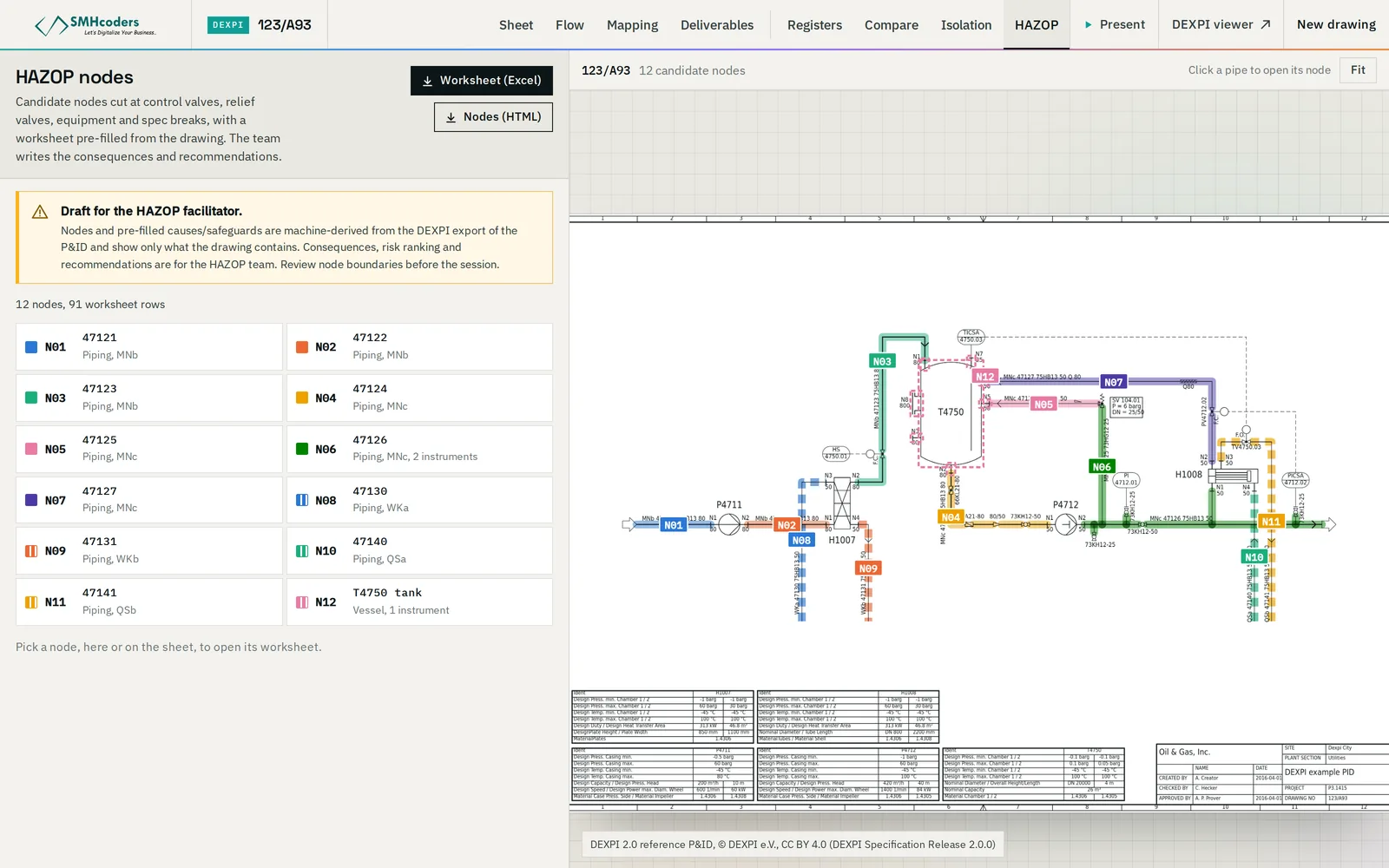
Record each node with its P&ID numbers, its boundaries (named valves, nozzles or tie-in points), its design intent with numbers — flow range, operating and design pressure and temperature, normal level, composition — and the operating modes to be studied (normal, start-up, shutdown, regeneration). Mark the boundaries on the drawings in colour; the marked-up set is what the team works from.
Writing the design intent
The design intent is what the deviations are measured against, so a vague one weakens every row that follows. Compare two descriptions of the same node:
Pump discharge line.
Transfer stabilised crude from the tank by P-101 (one duty, one standby) to the cooler at 40–55 m³/h, 12–14 barg and 45–60 °C, flow controlled by FV-101. Design 20 barg at 90 °C. Normal operation, start-up of the standby pump and pump changeover are in scope.
(Illustrative node and numbers.) The second tells the team what "more flow", "less pressure" or "higher temperature" means for this node, which operating modes to cover, and where the design limits are. Taking the numbers from the heat and material balance and the line list before the session saves the first ten minutes of every node.
Which guide words apply
Not every guide word applies to every parameter, and a prepared matrix keeps the session from mechanically reading out combinations that mean nothing. For a typical continuous-process node:
| Parameter | Guide words usually examined |
|---|---|
| Flow | No, more, less, reverse, as well as (contamination), other than (wrong material) |
| Pressure | More, less |
| Temperature | More, less |
| Level | More, less (and no, for a vessel that can run dry) |
| Composition | As well as, part of, other than |
| Operations | Start-up, shutdown, maintenance, sampling — studied as modes or as an "other than normal" step |
The facilitator adjusts the matrix per node; batch and sequential steps add the time and sequence guide words.
What the P&ID tells you in advance
A large part of a worksheet's left-hand side can be read from the drawing before the session:
- Parameters that apply. A node with a level instrument and a vessel has level deviations; a node with a heater has temperature deviations.
- Equipment-driven causes. A control valve failing open or closed (its fail action is on the sheet), a pump stopping, a block valve closed in error, a check valve failing to close, a heat exchanger tube leak, loss of cooling medium.
- Connections to other nodes. Where flow comes from and goes to, so that a "no flow" in one node is traced as a cause in the next.
- Safeguards shown on the drawing. Instrument letters tell you a lot: an A means an alarm function, an S a switch, often a trip, an H or L a high or low point; relief valves, check valves, controllers and interlocks are drawn.
What the drawing does not give you: alarm and trip settings, the cause-and-effect logic of the shutdown system, relief valve sizing cases, operating procedures, process conditions and the plant's own incident history. Those come from other documents, and from the people in the room.
What to pre-fill, and what to leave
| Worksheet column | Prepare in advance? | Why |
|---|---|---|
| Node, design intent, parameters | Yes | Facts from the drawings and process data; the team confirms them at the start of the node |
| Deviations (guide word × parameter) | Yes | The matrix follows from the parameters that apply |
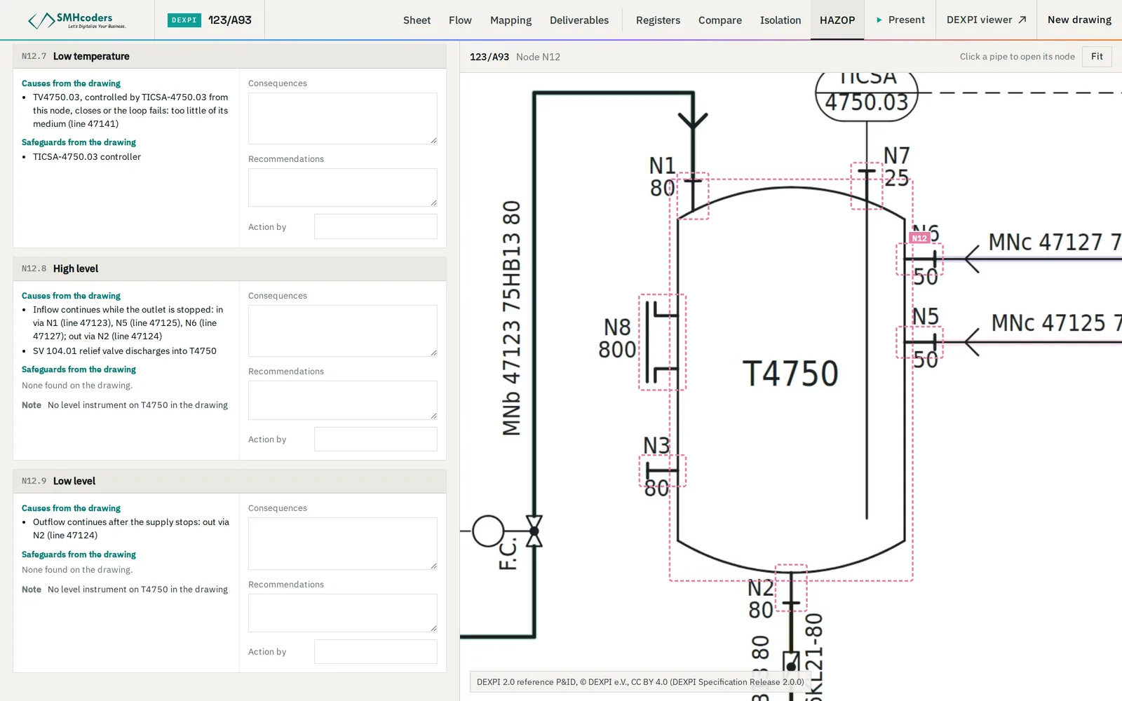
| Causes | Draft only | Equipment-driven causes can be listed; the team adds human, procedural and external causes |
| Safeguards | Draft only | The drawing shows what exists; whether it is effective for this cause is the team's call |
| Consequences | No | Need process knowledge, inventories and judgement |
| Risk ranking | No | Applied by the team against the site's risk matrix |
| Recommendations, action owners | No | The output of the study, not its input |
Pre-filling has one real danger: anchoring. A team handed a neat list of causes and safeguards tends to check it rather than think beyond it. Two habits counter that. Mark every pre-filled entry as a draft, visibly. And have the facilitator ask, for every deviation, "what else?" before reading out the prepared causes.
A cause with no safeguard on the drawing should be shown as exactly that — a gap for the team to discuss — not as a finding. Sometimes the protection exists in a procedure or in the control system and simply is not drawn; sometimes it does not exist.
A preparation checklist
- The current, issued P&IDs — confirm revisions with document control; note open MOCs on the unit.
- The node list with boundaries, design intent and operating modes, and the marked-up drawings.
- Process data: heat and material balance, design and operating conditions per node.
- Safeguard information: alarm and trip schedule, cause-and-effect charts, relief valve data.
- Previous HAZOP report and the status of its actions, for a revalidation.
- The site's risk matrix and the study's terms of reference.
- The draft worksheet, clearly marked as a draft.
Where software helps
Marking nodes on the drawings and listing what each contains is days of careful drawing-reading on a large study. With the P&IDs as a connected model, it can be prepared in hours and checked by the facilitator. Our HAZOP Prep proposes candidate nodes from a DEXPI model, lists the alarms, trips, relief valves, check valves and controllers in each, and pre-fills a guideword worksheet with the causes the drawing implies. It does not assess consequences, rank risk or make recommendations — those belong to the team — and output from converted drawings is verified against the issued drawing before the session. It is a draft for the facilitator, not a HAZOP.
 SMHcoders engineering teamAbu Dhabi · first published 20 Nov 2026 · updated 20 Nov 2026