
Line list and instrument index from P&IDs (free Excel template)
Line lists, valve lists, instrument indexes and equipment lists are the registers every project and plant keeps — and most of them start as someone reading P&IDs and typing. This guide covers what each register holds, how its columns map to the drawing, the checks that catch the usual errors, and a free Excel template to start from.
Four registers, one source
A P&ID set is the master for four registers that most projects and operating sites maintain:
- Line list — one row per pipeline (or line segment between spec breaks): line number, nominal size, fluid, piping class, where it runs from and to, and the design and test conditions. Piping, stress, insulation and inspection all work from it.
- Valve list — every manual, control, check and relief valve with its type, size, line and duty. Procurement, maintenance and isolation planning use it.
- Instrument index — every instrument tag with its function, loop, service, location and signal type. It drives instrument data sheets, I/O lists, loop drawings and the control system database.
- Equipment list — every item of equipment with its type, description and the nozzles and lines that connect to it.
Some columns can be read directly off the P&ID. Others come from process data, instrument data sheets or the piping specification. Knowing which is which is the first step to keeping a register that agrees with the drawing.
Download the free P&ID register template (Excel, .xlsx) — line list, valve list, instrument index and equipment list sheets with drop-down lists for the coded columns and a README. Free to use and adapt.
Reading a line number
Most projects encode a line's key attributes in its number. The format is set in the project's piping or numbering procedure, so there is no universal pattern — but a typical one looks like this:
When building a line list from P&IDs, parse the number into its parts rather than storing it as one string. That makes it possible to check the parts against the drawing — a 6" line number on a segment drawn with a 4" reducer before it is worth a question — and against the piping class list.
Two rules cause most line-list arguments. Where does one line end and the next begin? Usually at equipment nozzles, at changes of piping class (spec breaks) and where the numbering procedure says so. And how are branches numbered? Agree both before anyone starts typing.
Line list: what the drawing gives you
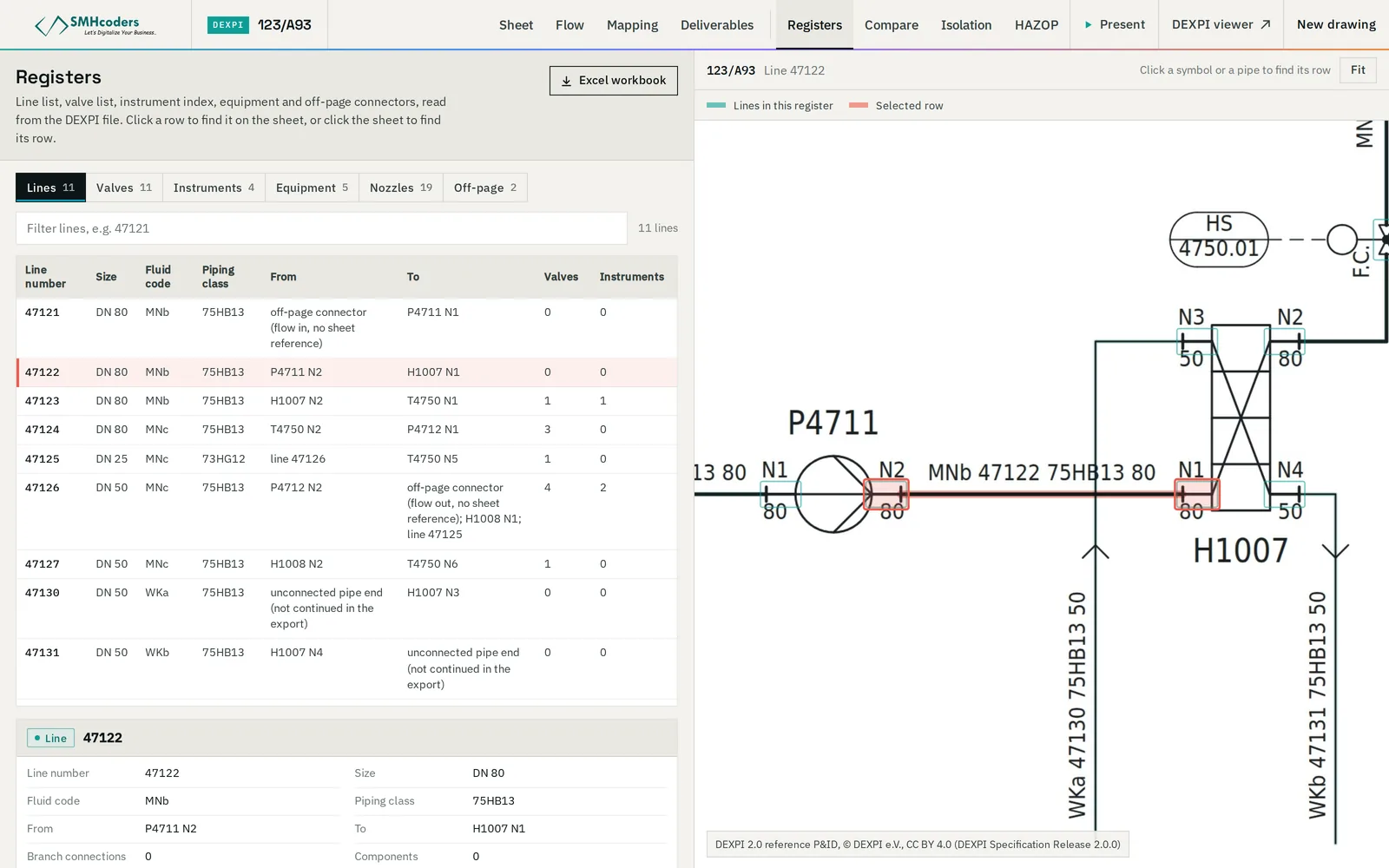
| Column | From the P&ID? | Notes |
|---|---|---|
| Line number, size, fluid code, piping class | Yes | Parsed from the line label; check the size against reducers on the line |
| From / to | Yes | Equipment nozzle, another line, or an off-page connector — follow the connector to the continuation sheet |
| P&ID number(s) | Yes | A line crossing sheets lists every sheet |
| Insulation and tracing codes | Often | When the project puts them on the label or as symbols |
| Design and operating pressure and temperature | Rarely | From the process data or line designation tables; sometimes noted on the sheet |
| Test pressure and medium, PWHT, NDE category | No | From the piping class and pressure-design rules |
Instrument index: decoding the bubble
Instrument tags on most Gulf projects follow ANSI/ISA-5.1 (current edition 2024). The letters in the bubble are a code: the first letter is the measured or initiating variable, an optional modifier follows it, and the succeeding letters are the functions. PDIT is a pressure (P) differential (D) indicating (I) transmitter (T). TIC is a temperature indicating controller. The number below the letters is the loop number, shared by every instrument in the loop.
The bubble's shape and the line across it tell you where the function lives: a plain circle is a field-mounted instrument; a line across it means it is accessible to the operator in the main control room; a circle inside a square is a shared display or control function (typically the DCS). Those distinctions go into the index's location column and decide whether an instrument appears on the I/O list.
From the P&ID you get tag, function letters, loop, the line or equipment the instrument sits on, the location class and the signal type implied by the line style. Range, set points, alarm limits, I/O type and the instrument's make come from data sheets and the control narrative.
Valve list and equipment list
For each valve, the drawing gives the tag (where the project tags manual valves), the type from the symbol (gate, globe, ball, butterfly, check, relief), the size, the line, and for control valves the actuator and fail action (FO / FC / FL) shown beside the body. Normal position — locked open, normally closed — appears as a note or a symbol code on many sheets and matters later for isolation planning.
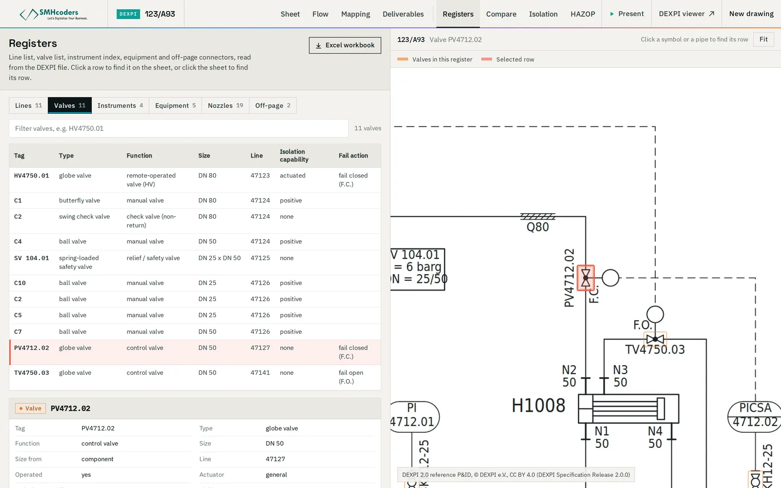
The equipment list takes tag, type and description from the symbol and its label, plus the nozzles and the lines on each. Sizing and design data come from the equipment data sheets, though a DEXPI export from a design tool may carry design pressures and temperatures with the item.
The errors that creep in
- Duplicate tags — two valves, or two instruments, with the same tag on one sheet or across sheets.
- Broken continuity — a line that leaves one sheet through an off-page connector and arrives on the next under a different number, or never arrives.
- Size and class mismatches — a line number that says 4" on a segment drawn after a reducer to 6"; a class that changes without a spec break symbol.
- Missing small-bore — vents, drains, sample points and instrument tappings left out because they have no line number.
- Instruments on the wrong line — a tapping drawn near a tee and assigned to the wrong branch.
- Stale rows — a revision deletes a valve and the register keeps it, because nobody re-read the sheet.
Each is cheap to test for once the register is in a structured form: duplicate tags with a pivot, continuity by matching every "to: off-page" with a "from: off-page" on the named sheet, sizes against the parsed line number, and row counts per sheet against a count of symbols on the drawing.
Using the template
The register template has one sheet per register and a Lists sheet holding the codes used in the drop-downs (sizes, valve types, fail actions, instrument locations, signal types, status). Replace the lists with your project's own codes first — fluid codes and piping classes are project-specific — and keep one row per object. A handful of example rows are filled in from the public DEXPI 2.0 reference P&ID (© DEXPI e.V., CC BY 4.0) to show the conventions; delete them before use.
Two habits make any register easier to keep right: record the P&ID number and revision each row was read from, and mark every value that did not come from the drawing with its source.
Reading the registers from the drawing instead
If the P&ID exists as a model — DEXPI from a design tool, or a converted drawing — the registers are a view of it, not a separate document. Our Registers tool reads the line list, valve list, instrument index, equipment list and off-page connectors from a DEXPI model into one Excel workbook, with every row linked to its object on the sheet so any value can be checked against the drawing. When the drawing changes, the registers are rebuilt, not edited. Attributes the drawing does not hold are left blank, not guessed, and output from converted drawings is verified against the issued sheet before a register is issued.
 SMHcoders engineering teamAbu Dhabi · first published 20 Nov 2026 · updated 20 Nov 2026