
P&ID digitisation: turning legacy drawings into data
Most operating plants run on P&IDs that exist only as PDFs, scans or CAD lines. Digitising them means turning each sheet into a model a computer can query — every valve, line and instrument with its attributes and connections. This guide covers what that involves, what accuracy really means, and how to plan it for an archive.
A picture of a P&ID versus a P&ID as data
To a person, a P&ID is unambiguous: a pump discharges through a check valve and a block valve into a line numbered on the sheet, and a transmitter on that line feeds a controller. To a computer, a PDF of the same sheet is a set of strokes and text fragments in no particular order. A scan is less still — a grid of pixels. Nothing in either file says that the two triangles touching at a point are a valve, or that the line leaving the pump is the same line that enters the exchanger on the next sheet.
An intelligent (or "smart") P&ID is one where that knowledge is stored with the drawing. Each object has a class (centrifugal pump, gate valve, pressure transmitter), a tag, attributes (nominal size, piping class, fail action, set pressure) and connections to the objects either side of it. Lines are networks rather than strokes, so you can ask what is upstream of a valve, which instruments sit on a line, or which block valves close off a pump.
Plants designed in the last two decades with a database-driven P&ID tool usually have this model somewhere, even if the operator only received PDFs at handover. Older plants — and many newer ones after years of mark-ups, as-built corrections and contractor turnover — have only the picture. Digitisation is the work of getting from the picture back to the model.
Why owners and contractors do it
The drawing set is the reference for almost every engineering activity on a plant, and most of those activities start by retyping parts of it:
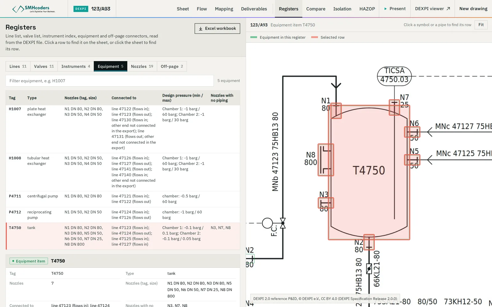
- Registers. Line lists, valve lists, instrument indexes and equipment lists are rebuilt by hand from the sheets and drift away from them with every revision. (See line lists and instrument indexes from P&IDs.)
- Revision review. Comparing two issues of a sheet by eye misses what the drafter did not cloud. (See P&ID revision comparison.)
- Safety studies and maintenance. HAZOP node preparation and isolation planning are drawing-reading exercises done under time pressure. (See HAZOP preparation and isolation planning.)
- Digital twins and asset information. An asset register, a simulation model or a twin needs the plant's topology, and the P&IDs are usually the only complete source of it.
The business case is rarely the drawings themselves. It is the hours spent re-reading them, and the errors that come from registers and studies that no longer agree with the sheet.
Four starting points, four different jobs
"Digitise our P&IDs" covers very different amounts of work depending on what the archive holds. Sort the sheets by format before estimating anything.
| What you have | What the file already knows | What has to be recovered |
|---|---|---|
| Database P&ID tool (native project) | Objects, tags, attributes, connections | Usually nothing: export DEXPI or a neutral format directly, then check the export |
| DXF / DWG drawn as lines and blocks | Exact geometry; block names often identify symbols; text is text | Which blocks are which objects, which lines connect to what, how text belongs to objects |
| Vector PDF (exported from CAD) | Exact strokes; usually real text | Symbols from stroke patterns, all connectivity, text association |
| Scanned sheet (raster) | Pixels only | Everything: clean-up, symbols, text by OCR, lines, connectivity — on degraded, skewed, marked-up images |
Two points matter for planning. First, the same symbol library and drafting standard usually runs through a whole archive, so the first sheets of a set are the expensive ones. Second, scan quality and paper size drive the effort on raster sheets far more than drawing complexity does: an A1 sheet scanned cleanly at 300 dpi is a different problem from an A3 reduction of the same sheet photocopied twice.
What gets extracted
A useful digitisation recovers four kinds of information, and each has its own failure modes.
Symbols
Equipment, valves, instruments, fittings, reducers, spectacle blinds, off-page connectors. The symbol set is defined by the project's legend sheets, which normally follow ISA-5.1 for instrumentation and ISO 10628-2 or a company standard for equipment and piping components — with local variations. A detector that has never seen a company's handwheel style will either miss it or call it something close. The honest output for an unrecognised symbol is "unknown, please classify", not a guess.
Text and tags
Equipment tags, instrument bubbles (function letters above, loop number below), line numbers, valve tags, set pressures, notes and holds. Reading the characters is the easy half. The harder half is association: which text belongs to which object, and parsing it — a line number carries size, fluid code, sequence number and piping class in one string, in a format each project defines.
Connectivity
Which object connects to which, through which nozzle or port, in which flow direction; process lines kept apart from signal lines; branches, crossings that do not connect, and continuations to other sheets through off-page connectors. This is where most of the engineering value sits — and where errors are least visible, because a drawing re-rendered from a slightly wrong model still looks right at a glance.
Title block and sheet metadata
Drawing number, revision, dates, approvals, project and unit references. Without them, a model cannot be placed in a document control system or compared with its next revision.
How the pipeline fits together
Whatever the tooling, the work has the same shape. Symbols are found and classified. Text is read and associated with the symbols and lines it labels. Lines are traced and joined into networks, with each end bound to a nozzle, a valve port or another line. The result is assembled into a model — ideally in an open format such as DEXPI, so it is not locked into the tool that made it — and checked before anyone relies on it.
Accuracy: what to measure, and against what
Vendors quote accuracy figures freely. Before comparing them, ask three questions.
Accuracy of what? Symbol detection, symbol naming, text reading, text association and connectivity are separate measures. A sheet can have 99% of its symbols found and correctly named and still have a line connected to the wrong nozzle — which is the error that matters for an isolation or a HAZOP.
Against what truth? The usual measures are precision (of the things the tool found, how many are real and right) and recall (of the things on the sheet, how many the tool found). Both need a ground truth: a set of objects someone has checked by hand. Ask who made it, on how many sheets, and whether those sheets were also used to tune the tool. A figure measured on the drawings a system was developed against is a regression test, not a forecast for your archive.
On what kind of input? Results on clean vector PDFs do not carry over to scans. Ask for figures by input type, and for the weakest sheet, not only the average.
Two practical checks are worth building into any project:
- Re-draw and compare. Regenerate the sheet from the extracted model and overlay it on the original. Anything the model lacks shows up as ink on one side only. It is a coverage check, cheap to run on every sheet.
- Rule checks. Validate the model: every piping segment has two ends, every nozzle connects, tags are unique, required attributes are present. A file can pass a schema check while modelling almost nothing — conformance is not coverage — so the rules have to test the content, not just the file structure.
Then put an engineer on whatever the checks flag. Machine extraction moves the engineer's job from transcribing to reviewing; it does not remove it. The issued drawing stays the document of record until the model has been accepted.
Standards worth knowing
- DEXPI — the open exchange standard for P&ID data, maintained by DEXPI e.V. Version 2.0 (October 2025, updated to 2.0.1 in September 2026) uses its own XML format; the 1.x versions use Proteus XML. What is DEXPI?
- ISO 15926 — integration of life-cycle data for process plants including oil and gas production facilities. The DEXPI data model is based on it.
- ISO 10628 — diagrams for the chemical and petrochemical industry: Part 1 specifies the diagrams, Part 2 the graphical symbols.
- ANSI/ISA-5.1 — instrumentation and control symbols and identification (current edition 2024): the bubble shapes and tag letters on most P&IDs in the Gulf.
- Your own legend sheets and numbering procedure — the standard that actually governs your drawings. Collect them before anything else.
Scoping an archive
A drawing archive is digitised in batches, and the first batch decides the method for the rest. A workable sequence:
- Inventory. Count sheets by format (native, DXF, vector PDF, scan), paper size, scan quality and unit. Note which sheets are as-built and which are known to be out of date — digitising a superseded sheet faithfully is wasted effort.
- Decide what you need out. Registers only? A full model with connectivity? A re-drawn, clean CAD sheet? DEXPI for a twin or a HAZOP tool? Each output has its own acceptance test, and each adds review time.
- Pick a pilot set that hurts. Five to ten sheets including the worst scans, the densest sheets and every legend sheet. A pilot on clean, simple drawings tells you nothing about the archive.
- Agree the acceptance gate up front. For example: every equipment item and valve present; tags read correctly; every process line connected at both ends; unknown symbols listed, not guessed. Agree how it will be checked — by whom, against which sheets, with what sampling for the bulk of the archive.
- Prioritise by use. Units heading for a turnaround, HAZOP revalidation or a modification project go first: the model pays for itself on its first use.
- Plan for revisions. A digitised sheet starts going stale with the next MOC. Decide where the model will be maintained — in the native design tool, or regenerated from each new issue — before converting thousands of sheets.
Build or buy
The parts are available: OCR engines, object-detection models, CAD libraries, and open-source DEXPI tooling such as pyDEXPI. An in-house team can assemble a prototype that works on its own sample quickly. What takes the time is everything after the prototype: symbol libraries per drafting standard, line tracing that survives scans and crossings, text association, a DEXPI export that other tools accept, measurement against a ground truth, and a review interface an engineer will actually use.
If you buy, ask the vendor to convert a sheet you choose, and ask:
- How is accuracy measured, on what ground truth, and what was the weakest result?
- What happens to a symbol the library does not know?
- What is the output — an open format such as DEXPI, registers, a re-drawn CAD file — and does the tool's own export pass an independent validator?
- Where do the drawings go, and can it run inside your network if they may not leave it?
- When the next revision is issued, is it a re-run or a new project?
Where P&ID Studio fits
Our P&ID Converter takes PDF exports, scans and DXF, reads symbols against your library, resolves connectivity and the title block, re-draws the sheet from the model to measure fidelity, and puts an engineer's review before release as DEXPI 2.0, 1.4 or 1.3 and a re-drawn DXF. The rest of P&ID Studio works on that model — or on DEXPI exported from your design tool. Its output is machine-extracted engineering data: it is verified against the issued drawing before anyone relies on it.
 SMHcoders engineering teamAbu Dhabi · first published 20 Nov 2026 · updated 20 Nov 2026