
Isolation planning from P&IDs: finding the isolation points
Before a pump is opened, a valve replaced or a vessel entered, someone has to work out from the P&IDs every point where process fluid could reach the job, and how each will be closed, proved and drained. This guide covers how isolation points are read off the drawing, the isolation standards they are judged against, and what software can and cannot do in that process.
What an isolation has to achieve
Intrusive work on process plant — breaking a flange, removing a pump, entering a vessel — needs the equipment separated from every source of hazardous energy and material: process fluid under pressure, flammable or toxic inventory, heat, and the electrical and mechanical energy that could start a machine. Isolation is planned, applied, proved and recorded within the site's permit-to-work system; the UK HSE's HSG250 sets out how such systems work in the petroleum and chemical industries.
The same principle appears as lockout/tagout (LOTO), the term used in the US standard 29 CFR 1910.147, "The control of hazardous energy (lockout/tagout)": isolating devices are locked and tagged so that energy cannot be restored while people are working. On process plant, the process side of an isolation — which valves, which spades, which vents — is read from the P&IDs.
Positive, proved and non-proved isolation
The HSE guidance HSG253, The safe isolation of plant and equipment (2006) groups process isolation methods into three categories, and many company isolation standards use the same structure:
- Positive isolation — complete separation of the equipment from the rest of the system: a spade or spectacle blind fitted, a spool piece removed, or a physical disconnection leaving an air gap.
- Proved isolation — valved isolation whose effectiveness can be confirmed through vent or bleed points. Double block and bleed is the familiar form: two block valves in series with a bleed between them, opened to show that the first valve is holding.
- Non-proved isolation — a single valve, or two valves without a bleed, with no way to confirm the isolation is holding. Where it is used at all, a double valve is preferred to a single one.
The choice between them is a risk-based decision made against your company's isolation standard, weighing the substance, its pressure and temperature, the line size, how long the work lasts and what would happen if the isolation failed. A P&ID cannot make that decision. What it can tell you is what the plant allows: whether there are two block valves in series with a bleed between them, whether there is a spectacle blind or a spool, and where the vents and drains are.
Reading the P&ID for an isolation
Start from the item to be worked on and walk outward along every connection until each path reaches a valve that can isolate it. On a typical pump that means suction and discharge, but also the minimum-flow recycle, the warm-up or balance lines, seal and flushing connections, the casing vent and drain, and any instrument tapping on the pump's own nozzles. On a vessel it can be a dozen paths.
The paths most often missed are the small ones:
- Bypasses around control valves and block valves — an isolation that closes the main line and leaves the bypass open is no isolation.
- Small-bore connections — vents, drains, sample points, chemical injection points and pressure gauge tappings.
- Relief valves — both the inlet, which connects the equipment to its own overpressure protection, and the outlet, which connects it to a flare or vent header shared with other equipment.
- Utility connections — nitrogen, steam-out and flushing connections, often drawn as small stubs with a blind or a hose connection.
- Cross-ties and spares — a common suction header to a duty and a standby pump.
Which valves count
A boundary has to be a valve that is designed to shut off, can be locked in position and is in a suitable condition. On the drawing, check each candidate:
- Manual block valves (gate, ball, plug, globe) are the normal boundary.
- Control valves are not designed for tight shut-off and move when their signal or air supply changes; HSG253 notes that control and choke valves are not generally suitable for isolation. The walk carries on past them to the next block valve.
- Check (non-return) valves close only when flow reverses and cannot be locked shut. A plain check valve is not an isolation; a screw-down non-return valve, closed by its handwheel, is a different case.
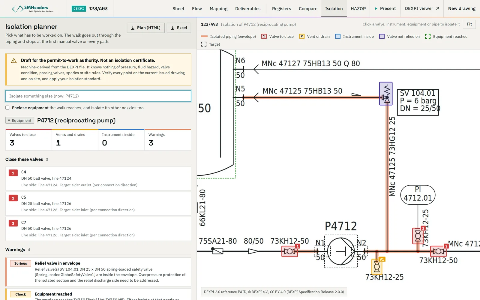
- Relief valves are protective devices, not isolations, and should not be relied on as boundaries.
- Actuated on/off valves — shutdown valves, motor-operated valves — can serve if the site's standard allows it and the actuator is itself isolated and locked; the P&ID shows the actuator but not the procedure.
Vents, drains and proving
Once the boundary is closed, the trapped section has to be depressurised, drained and, for flammable or toxic service, flushed or purged. The vents and drains inside the envelope are how that happens, and they are also how a valved isolation is proved — a bleed that stays at zero pressure shows the upstream valve is holding. List them with the boundary valves. If an envelope has no drain or vent inside it, the drawing is telling you the isolation plan needs a temporary connection or a different boundary.
Instruments and root valves
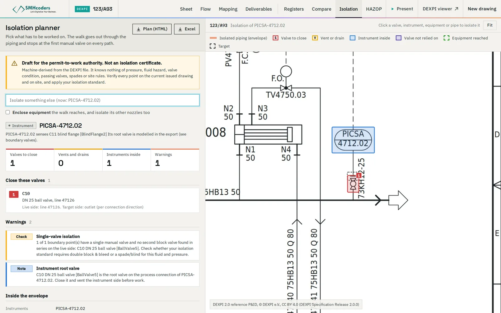
Transmitters and gauges connect to the process through a root valve at the tapping and, often, a manifold at the instrument. Working on the instrument means isolating at the root valve and venting the impulse line; working on the line means remembering that every instrument on it is a path to the job. The P&ID shows the tapping and, depending on the project's drafting standard, the root valve — a sheet that does not draw root valves will not tell you where they are.
Where the sheet ends
An isolation envelope does not stop at the sheet border. When a path leaves through an off-page connector, the boundary is on another drawing — and the envelope cannot be completed, or checked, from this sheet alone. Mark the connector, open the continuation sheet and carry on. Isolation drafts that silently stop at the edge of the sheet are among the most dangerous paperwork errors, because they look complete.
Writing the isolation list
However it is prepared, the isolation is recorded as a list the isolation authority and the people applying it work from. For each point, a good list states:
- the tag and the P&ID (and sheet) it is on, with a description a technician can find in the field;
- what it is — block valve, spectacle blind, spool, vent, drain — and the position required: closed, open, spaded;
- which side is live and which is isolated;
- the isolation category it provides, against the site standard;
- how it will be proved — which bleed or gauge, what reading is expected;
- the lock and tag numbers once applied, and who applied and verified them.
Add the sequence: close the boundary, depressurise and drain through the named points, prove, then fit spades if required. The de-isolation sequence matters as much — reinstating in the wrong order can trap pressure or open a drain to a live system — and it is often the part written in a hurry.
What the drawing cannot tell you
- Valve condition. A valve that passes is not visible on a P&ID. Proving the isolation on site is what finds it.
- As-built status. The drawing may not match the plant; a walk-down confirms each isolation point.
- Other energy. Electrical isolation of a motor, stored mechanical energy, and heat come from other documents and other procedures.
- The hazard. The fluid's toxicity, flammability, pressure and temperature decide what level of isolation is required; the line number gives a hint, the process data gives the answer.
What software can do — and must not
Tracing every path outward from an item to the nearest block valves is mechanical work, and it is exactly the part where people miss a bypass or a drain at the end of a long shift. Software reading a connected P&ID model can do that walk completely: list every boundary valve and the side it isolates, list the vents and drains inside, pass through control and check valves and flag them, report single-valve boundaries, and stop with a warning at every off-page connector.
It must not decide. The output is a draft for the isolation authority, who selects the isolation method against the site standard, verifies the points on site, and signs. Our Isolation Planner is built on that line: it returns the envelope, the boundary valves, the vents and drains and the warnings, marked on the sheet — as a draft, not an isolation certificate, and with machine-extracted drawings verified against the issued, as-built P&ID.
 SMHcoders engineering teamAbu Dhabi · first published 20 Nov 2026 · updated 20 Nov 2026